PlaneMaker Work
Step 1 Project Structure
All ACF files in X-Plane must reside somewhere in X-Planes Aircraft folder. Best practice is to create a dedicated folder for your aircraft, give it a meaningful name and put all relevant files in the one folder. We call such a folder your ACF folder. Depending on the complexity of a project, your ACF folder may have many other sub-folders. Our project will only have one, the objects folder.
Create the two folders as shown below in the middle image, (Our Project Structure). Feel free to name the outer directory anything you like, but make sure the one inside is named objects. A mature project is also illustrated to show what other kinds of files and folders can potentially be included. Some of the files are created by X-Plane (preview icon and pref files), and other files by the author. CLICK on the link below to download a zip file with the 3 assets for the objects folder and put those 3 files in there. Ensure your objects folder matches Our Project Structure before you get to Step 9 below.
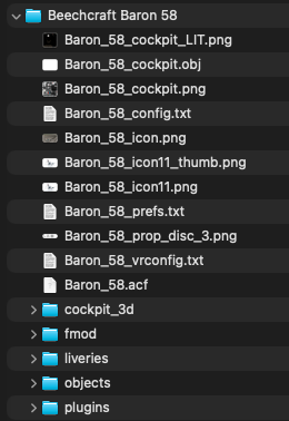
Mature Project Structure
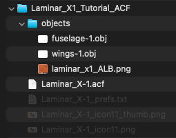
Our Project Structure
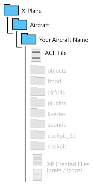
Possible Project Structure
Step 2: Minimum Data
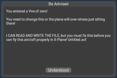
X-Plane requires a minimum amount of data entered in PlaneMaker in order to save your aircraft. If you do not have the minimum data entered in PM, then PM will give you a message when you try to save letting you know what is missing (example at right). This can be frustrating because there are a significant number of items to enter before you can save and the messages can be a bit confusing.
We are going to enter the minimum data first, so that we can avoid those confusing error message and you can save your file regularly as you work. The checklist below can be used as a guide to enter the minimum data. These items may not make much logical sense, but just know that X-Plane needs these values at minimum in order to load the aircraft. Click the links to the right of the Task to bring up a convenience image with the relevant data to enter.
| Task | Notes | |
|---|---|---|
| Launch Plane Maker | ||
| Create New File | Don't save yet, you'll just get warning messages! | |
| Name the Plane for UI | Standard > Author |
|
| Enter VNE Speed of 300 | Standard > Viewpoint > General Tab |
|
Enter Empty Weight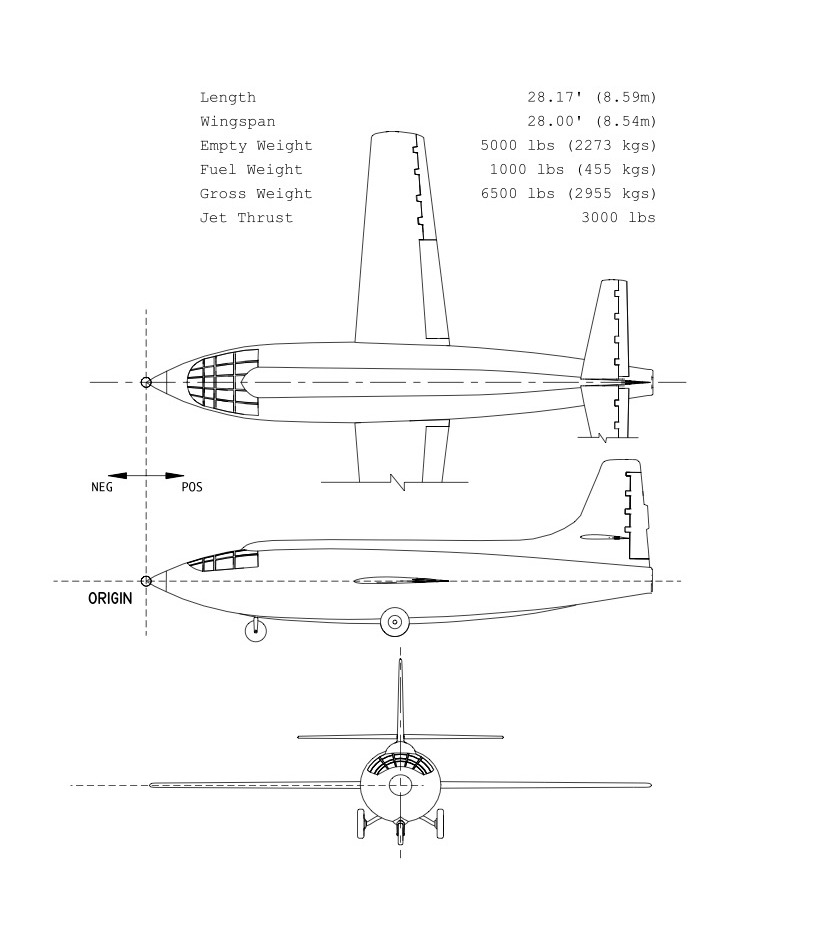 |
Standard > Weight & Balance > Weight/Bal Tab > Weights Panel |
|
| Enter Maximum/Gross Weight |
Standard > Weight & Balance > Weight/Bal Tab > Weights Panel |
|
Set Wing 1 Semi-Length 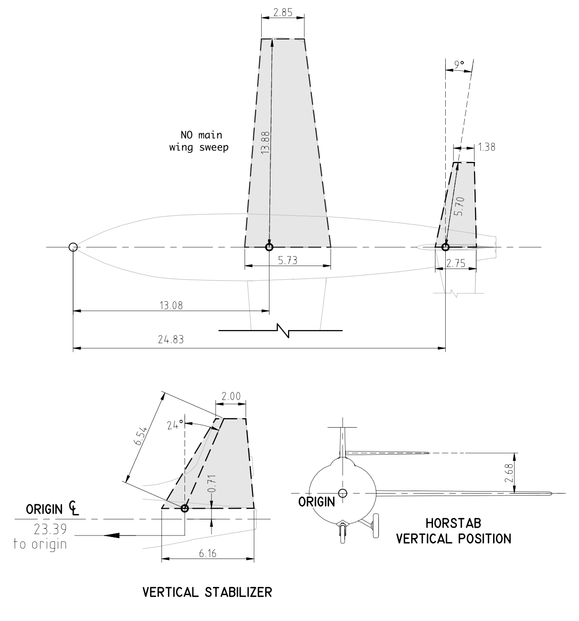 |
Standard > Wings > Wing 1 Tab |
|
| Set Wing 1 Root-Chord |
Standard > Wings > Wing 1 Tab |
|
| Remove Generator (Set to 0) | Standard > Systems > Electrical 1 Tab |
|
| SaveAs the Plane |
WARNING
With the minimum data above, you can now open the aircraft in x-Plane; however, nothing good will happen. At the very least, configure your landing gear before opening the aircraft in x-Plane, after which you may keep PlaneMaker and X-Plane open at the same time for the fastest editing workflow.
GEAR DATA
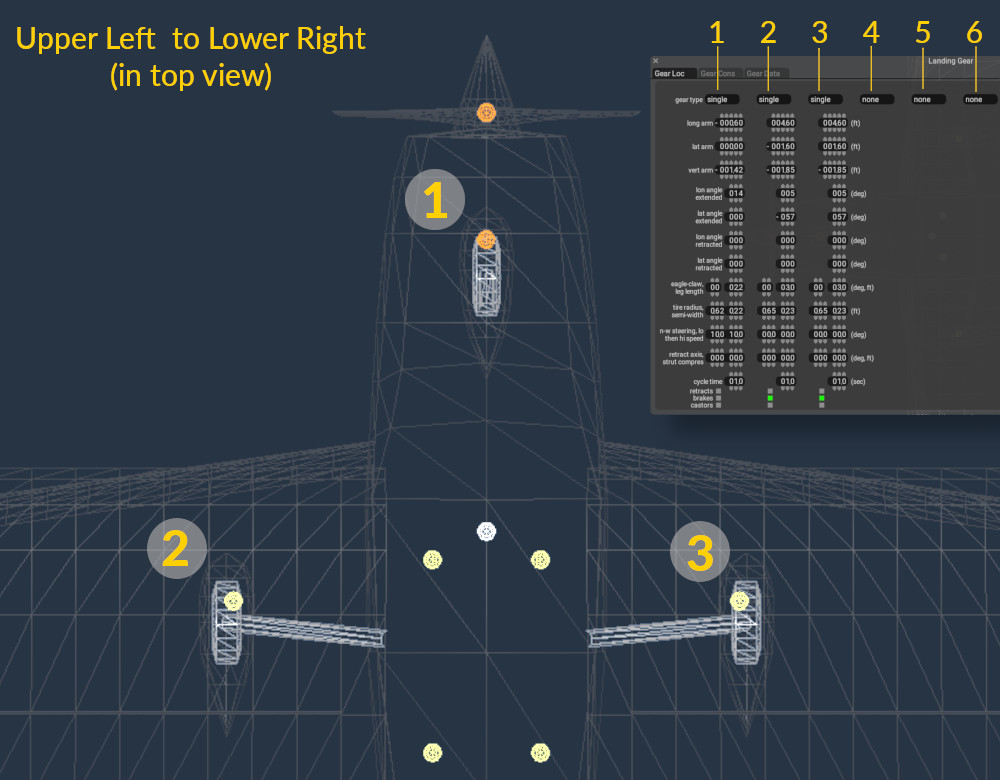
GEAR INDICIE ASSIGNMENT
Step 3: Landing Gear
Though you have successfully saved the aircraft and X-Plane can open it, there is not much for X-Plane to work with. The geometry will just flail around on the ground in X-Plane if you tried it. Because our goal is to get PlaneMaker and X-Plane open at the same time and make meaningful edits and check our results, we will configure the landing gear next so the aircraft can stand itself up.
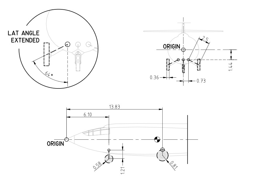
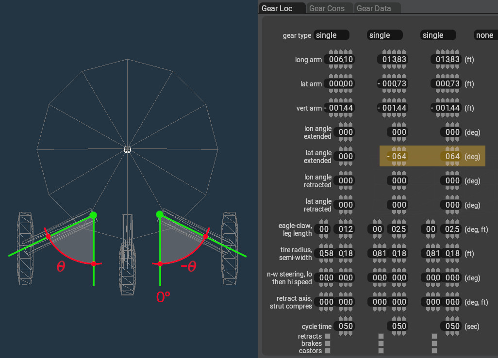
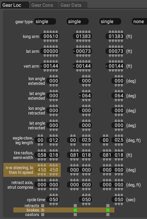
When you get to the Gear Configuration page, you will see three columns as shown above. ANY column can be configured for any landing gear; however, there is an unofficial standard where you view the aircraft from the top view, and when reading the image like a book, from top-left to lower-right, then the first column is used for the first gear you come to. For a tri gear, its the nosewheel, and for a tail-dragger, it would be the left main gear. Again, this is not required but has become a bit of a standard and is the way we will configure the gear. All the data fields to configure the gear are on one page. Go to the following page and configure the landing gear per the values given in the bullet list images. Pay attention to negative values!
MENU PATH: Standard > Landing Gear
- Set Gear Location
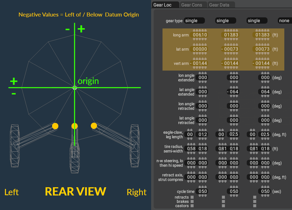 (The location represents the TOP of the gear leg (yellow dots)
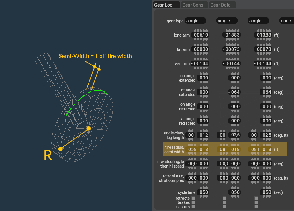
 - Set Tire Sizes
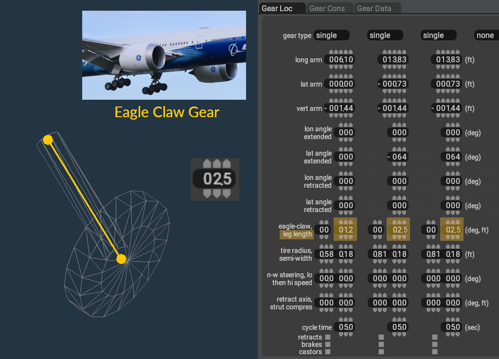
- Set Leg Length
- Set Leg Orientation
- Enable Steering / Braking
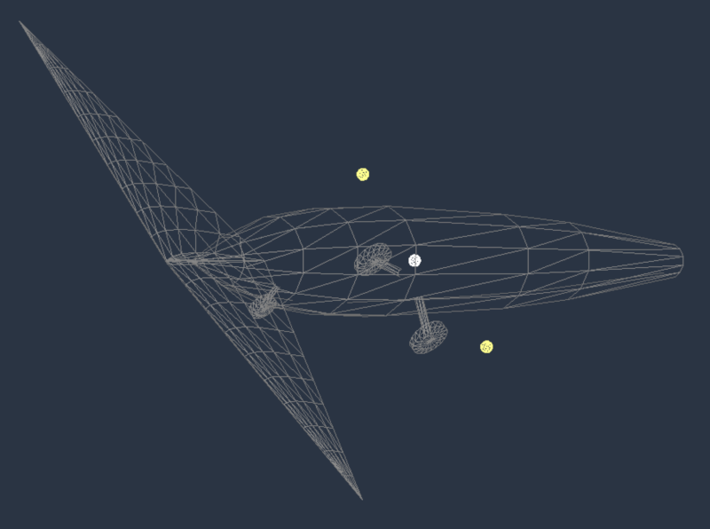
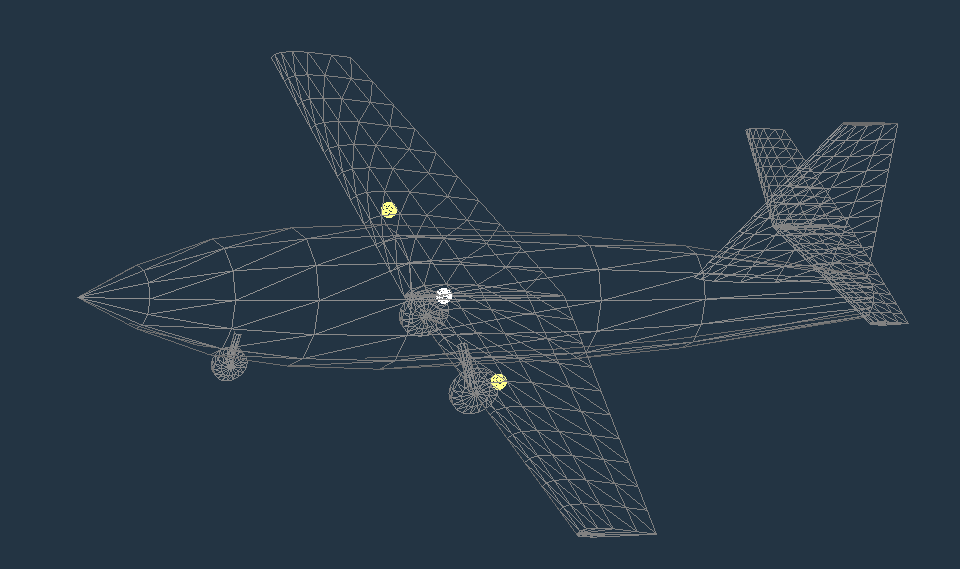
After minimum data & landing gear have been entered, the aircraft should appear as shown below. If you open it in X-Plane, it should stand on its gear; however, because the Center of Gravity (white dot) is not between the nose/main landing gear, the aircraft will tip over! Feel free to try it if you like. Next we configure the Center of Gravity to be between the landing gear so the aircraft will then be statically stable and can stand on its on in X-Plane while we continue to refine it.
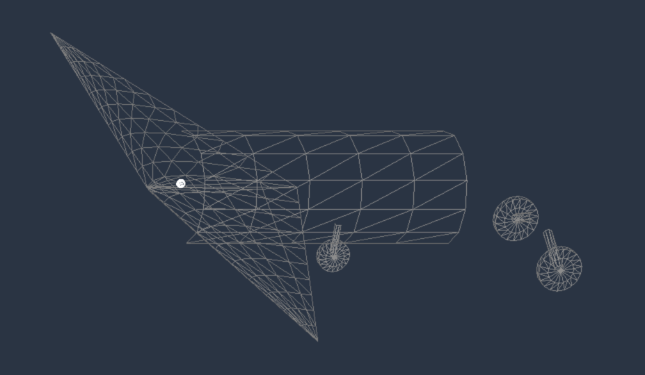

Click to Enlarge
Step 4: Inertial/Mass Loads
In this step we configure the Center of Gravity, define the fuel load, fuel tank locations and how much they hold, and configure a payload station for the pilot. Go to the following page.
MENU PATH: Standard > Weight & Balance > Weight/Bal Tab
- Configure the maximum Fuel Load/Weight
- Set the Empty Weight CG (Center of Gravity)
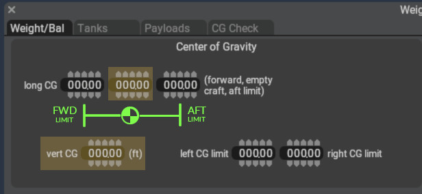 (see image at right for location)
- Set the forward limit 1 foot in front of the Empty Weight CG
- Set the aft limit 1 foot behind the Empty Weight CG
MENU PATH: Standard > Weight & Balance > Tanks Tab
- Configure Fuel Tanks
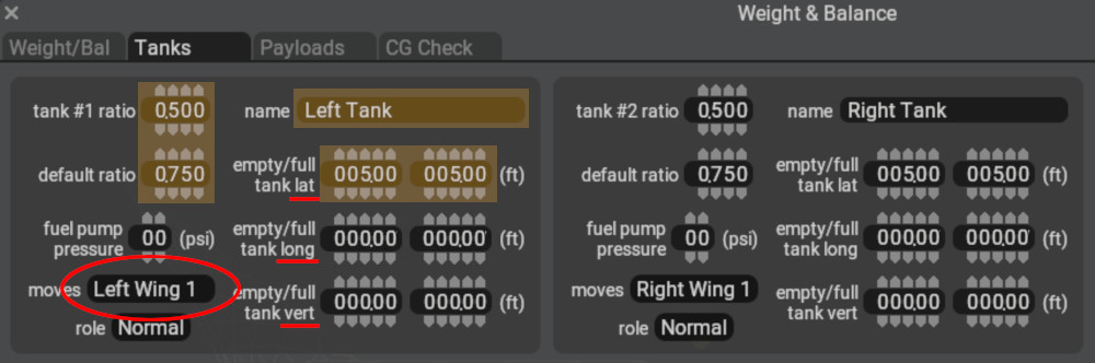
- Use the image at right to obtain the fuel tank lat/long/vert CG locations; HOWEVER, here is a PlaneMaker quirk! When you set the moves pulldown to one of the wings, then the (0, 0, 0) location of the fuel tank is RELATIVE to the wing reference point. In this way, when you move the wing around later on the Wings page, the fuel tank will move WITH the wing, and you do not have move the tank location every time you move the wing. This is why the LONG location is zero.
- Enter the same tank location values for both fields. Two fields are provided to simulate shifting CG as fuel burns. For our simple project, we assume the fuel CG does not change as fuel is consumed.
- The name of the tank is up to you, it appears in X-Plane's fuel management UI.
- Only one fuel tank is shown in the pop-up image above, which is configured to hold 50% of the total fuel. Configure a tank #2 ratio* by setting its tank ratio to 0.5, such that each tank can hold 50% of the total fuel. The total of all fuel tank ratios must add up to 1.
- The default ratio of each tank is how full THAT tank is when X-Plane starts. In this way, you can launch X-Plane with one tank having more fuel in it than another. A value of 1.0 means THAT TANK is full on X-Plane start. Each tank defaults to half-full.
MENU PATH: Standard > Weight & Balance > Payloads Tab
- Configure Payload Station for the PILOT
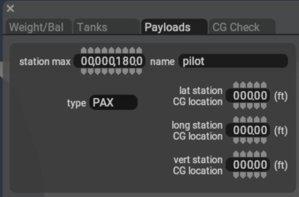
- Enter a non-zero station max value to show the other payload data fields for data entry.
- See image upper right for location of the pilot payload station. The station max is maximum weight for the payload station. X-Plane initializes the payload to a reasonable default less than this value, but you can use a slider in X-Planes UI to set this weight, after which it will be saved to your aircraft prefs file. The name you give the station appears in X-Planes UI.
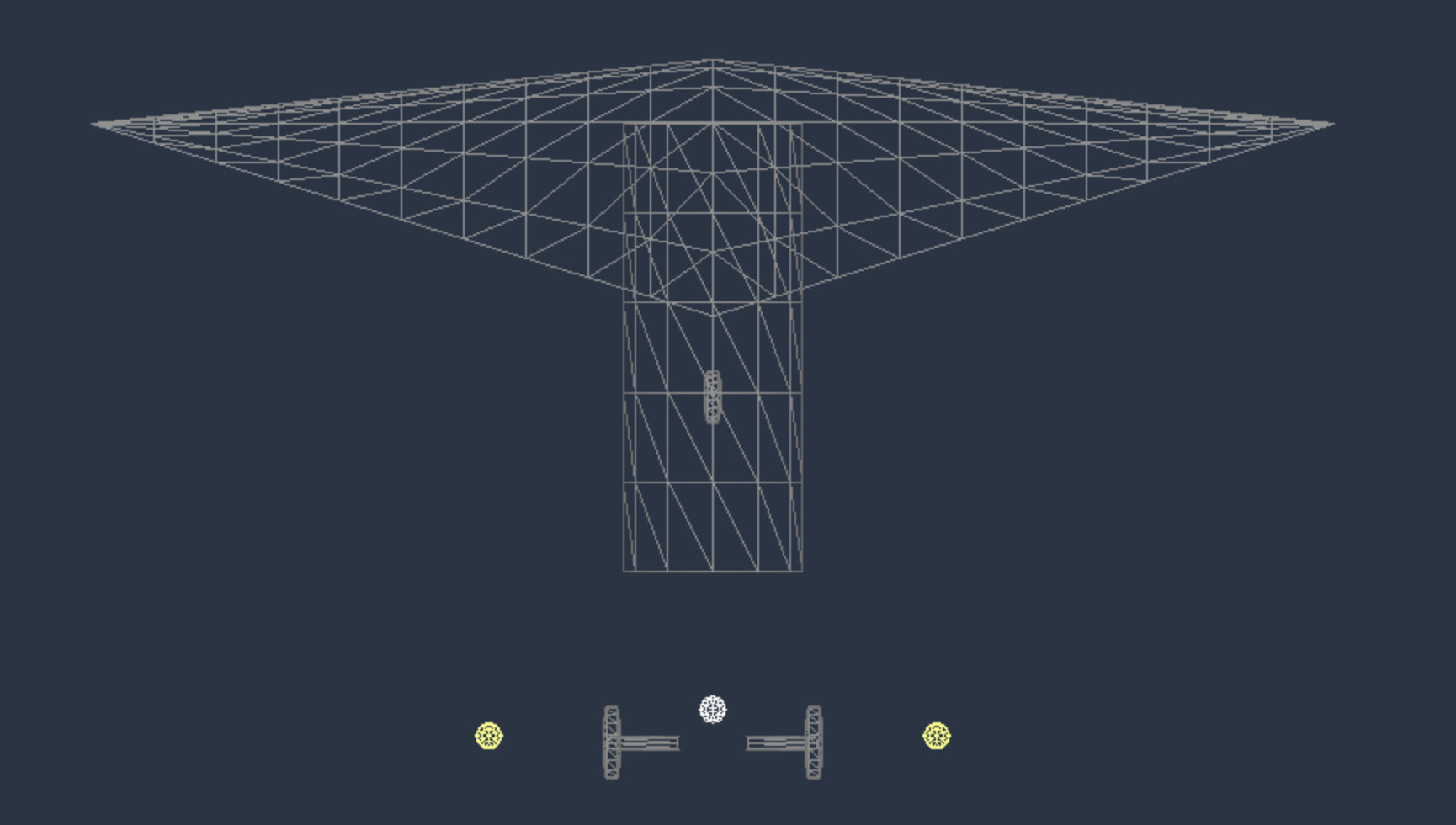
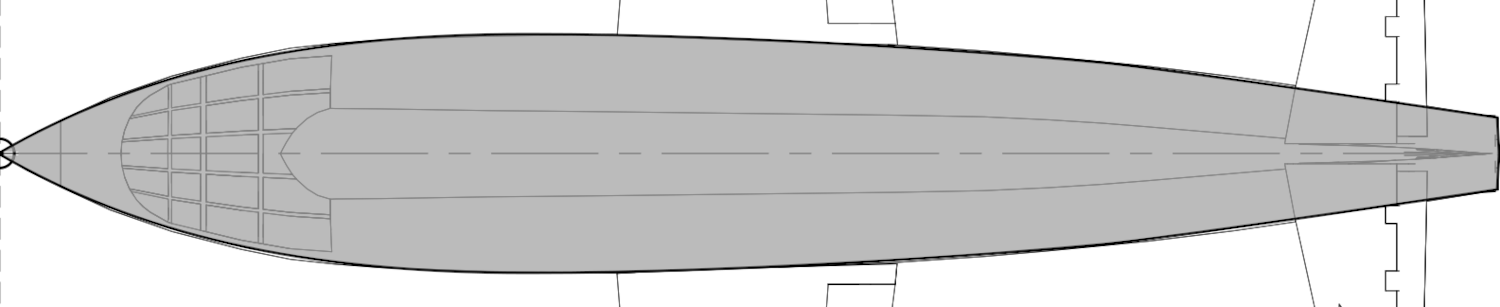
TOP VIEW: Click to Enlarge
At this juncture we can launch X-Plane and keep both it and PlaneMaker open at the same time while we work. If you prefer to only work in PlaneMaker and launch X-Plane after the aircraft is complete, then feel free to do so. Your aircraft should look as shown at right. If you've entered wrong numbers, or entered extra data in previous steps (wing tip chord for example), then your version may appear slightly differing.
Lets recap what we have in the image. We have a body (fuselage) and wings and three-point landing gear arranged with the Center of Gravity located so it won't tip over, and we have two fuel tanks located properly.
From here we'll shape the fuselage, configure the wings and stabilizers, add control surfaces and engine, and finally we will add eye candy 3D objects and some simple 2D Panel instruments.
Our workflow now will be to make changes in PlaneMaker, save the file, and then use X-Planes Menu: Developer > Reload the current Aircraft and Art to reload the aircraft in X-Plane without restarting the sim.
Launch X-Plane
Once you are in X-Plane, you can use keystrokes to view your work. See the View Keystrokes Section for commonly used keystrokes to examine your aircraft in an exterior view while editing. Lets move on to shaping the fuselage.
Step 5: Fuselage
NOTE
X-Plane has no concept of a Fuselage. Any non-lifting shape that is not associated with an airfoil is a body. Bodies are used to model fuselages, engine nacelles, wheel-pants, randar pods, etc. Body 1 in PlaneMaker is generally used to model the primary fuselage, though this is not required.
Shaping Bodies efficiently in PlaneMaker takes practice and PlaneMaker have techniques and tools to assist in the process. For the sake of time, we will not cover all the various functions and options available for shaping bodies, but rather simply execute the steps required for this tutorial. The upcoming PlaneMaker manual (still in development) will expand more on the various tools and techniques available to shape bodies.
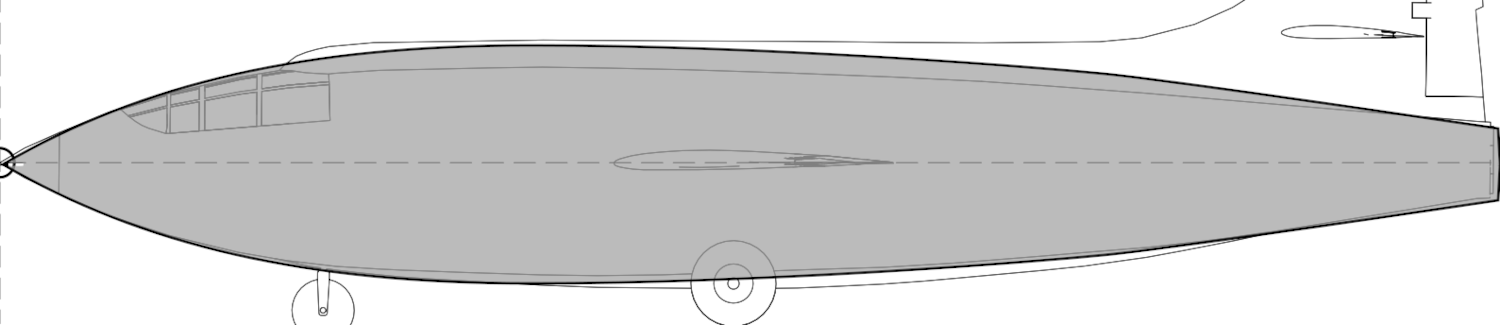
Click to Enlarge
In this step, we will shape the Fuselage (Body), which is one of the more time-consuming and challenging parts of aircraft modeling. We will use background images of the aircraft to use as guides in shaping the fuselage. Lets go to the Bodies page in PlaneMaker.
MENU PATH: Standard > Bodies > Body 1 Tab > Section Tab
Bounding Limits Configuration
Configuring Bounding Limits of the body sections first is simply a best practice. We locate the first section, the last, section and the maximum section dimension. This creates a type of bounding box within which we are more easily able to work with less visual clutter.
The first thing we do is estimate the number of sections we will need to reasonably capture the shape. PlaneMaker allows up to 20 sections per body. Then we configure the parameters that establish the bounding box limits for the body, that is the forward most section location, the aftmost section location and the maximum transverse dimension of the body (lateral or vertical). Once these steps are done, we begin shaping the individual sections to refine the shape. Again, you want to lock in those end section locations first, before shaping the interior sections.
- Set # Stations to 9
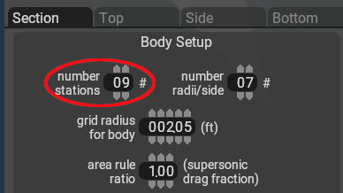 You can add/subtract sections if need be, but there's some awkwardness in doing so.
 - Set Grid Radius Diameter
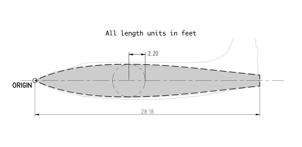
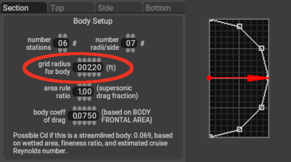 This controls the size of the section editing grid. It needs to be large enough to contain the widest/tallest section profile. The image upper right shows our maximum body section to be 2.20 feet.
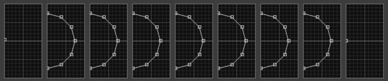
 - Configure Station Locations as shown in this image
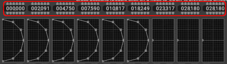 You will note that the last section and the one before it have the same dimension. We discuss this below.
 - Duplicate Sections
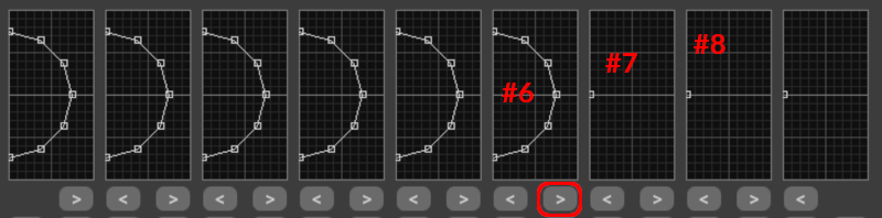 This button copies section profile to an adjacent section. You can copy left or right. Leave the last section as a point
 - Click ANYWHERE in the first section grid. This will cause the section to collapse to a point. Center the point vertically. Note that clicking anywhere in either the first or last section will always cause those sections to collapse to a point. Your fuselage body should now have the following section profiles.
 , and we are ready to begin refining the shape.
Click to Enlarge
If you rotate around the 3D view to look at the back of the fuselage, you can now see how the last two sections occupy the same location longitudinally (28.18 feet). Body drag is configured manually and is not a function of the body shape, so this apparently "closed off" tailpipe is not really closed off aerodynamically. Body shape affects lateral and sideslip aerodynamics, not drag. Its common for the last two sections to have the same longitudinal location for cylindrical tailpipe/exhaust shapes.
Background Images
Now we load in some background images as a general guide for our shaping. Download the following two images and place them in the root level of your aircraft folder. When you use background images, the reference shape should extend to the very left/right edges of the image. This will become important when using the Reset Editing Zoom button. Note that loaded background images are not saved between PlaneMaker sessions, they will have to be loaded in each run.
- BG Top Image
- BG Side Image
Now go to to the TOP tab of the Body 1 page: Standard > Bodies > Body 1 Tab > Top Tab
...and in the bottom left corner, select the Top Background Bitmap button and load BG_top_view.png.
Next go to the SIDE tab, and select and load the BG_side_view.png image the same as for the top view. This is a good time to SAVE your project if you have not in a while.
Whenever you are on any Body Tab view NOT the section tab, i.e. Top / Side / Bottom / Front / Back, then you will see a button labeled Reset Editing Zoom. Experiment with zooming in these views by using the plus/minus keys to zoom in and out, and also while holding down the SHIFT key modifier for faster zooming. Zoom in/out and then hit that Reset Editing Zoom button to see how it all works.
SPECIAL TIP![]()
The location of any section longitudinally (those numbers that you typed in earlier) is defined by the top vertex point. If you move only the top vertex forward or backwards in the top/side/bottom views, then hit either of the Reset to Vertical buttons, then all the other points in the section will align with the top vertex position. This is a quick technique to graphically move whole sections forward and backwards without having to edit their location on the section tab! This is a common technique whenever you use background images to shape bodies. The station locations that we typed in earlier were established using this visual technique.
Ellipse Smoothing Sections
There are many ways to shape each section. The most obvious is one point at a time, which is incredibly tedious work, but many folks do it. The "One point at a time" method is useful for crafting sections with sharp corners in their profile; however, for sections that are smoothly curved, then its helpful to use PlaneMakers two ellipse smoothing functions, which we do for this project. These tools are available only when the Body Editing window is active. The following two videos show these tools in action.
Section Smoothing Example (F1 key)![]()
The section smooth tool will smooth out all the sections. It uses the top, bottom and middle section points to define a bounding box and as the F1 key is repeatedly pressed, the section will morph into an ellipse inside the bounding box established by those 3 points. We will size the tailpipe section using this technique and performing the following actions.
| VIEW | ACTION |
|---|---|
| Top / Side View | align top/bottom/side points with the background images tailpipe edges. |
| Section View | hit the F1 key repeatedly (10+ times) and observe the tailpipe section morph into a circle. |
Note that Bodies are symmetrical left/right, but not top/bottom; therefore we have to set the top and bottom points in the side view, but only one point in the top view, either point (left/right) can be used. In addition, points within a section do not have to be planar/vertical; however, it is easier to visually shape the model if they are, especially when using the front/back views.
Total Body Smoothing
Whereas Ellipse Smoothing will only smooth the individual sections, Total Body smoothing will smooth the entire body longitudinally. In doing so, this smoothing operation will also affect the section profiles as well. The nominal procedure when shaping a body using smoothing is iterative, going back and forth between adjusting individual section control points (top / bottom / side control points) and tapping the F1/F2 keys in various views, adjusting points again, more F1/F2, etc. The video below shows the effect on a body when Total Body Smoothing
Total Body Smoothing Example (F2)![]()
NOTE
For sections with sharp corner points, you can double-click on a point in the section view to ***exclude it*** from the smoothing algorithm. We do not do that in this tutorial because our shape is smooth throughout.
Shaping Our Fuselage
Click to Enlarge
Its now your turn to shape the fuselage using these smoothing technique. Start by Total Body Smoothing the entire shape first (F2 key). Go to the TOP view and tap the F2 key perhaps 15-20 times until the shape is generally parabolic longitudinally. The shape will not perfectly align with your background image profile just yet.
Next, alternate between the top and side views and align the section ellipse control points with the background image and then the F1 key to smooth the shape until it matches the background image in both the top and side views. This part is like shaping clay. Remember this is iterative, you may have to move control points you moved previously because F2 Total smoothing affects the whole body; however, each iteration gets closer and closer and converges on the final shape. The video below shows a small sample of the technique. When done, your aircraft should look as shown at right. Good luck!
Example Shaping, Section by Section ![]()
Click to Enlarge
Step 6: Wings
In this step we are going to create the wing planforms and move them to their proper locations on the aircraft. All the information you need to define the wing and stabilizer plan is contained in the image at right and you will refer to that image to obtain the values to enter. Lets go to the wing configuration page.
MENU PATH: Standard > Wings > Wing 1 Tab
Wing Fundamentals & Nomenclature
Read though each bullet point below and become familiar with some wing concepts. These are fundamental concepts to know when configuring wings in PlaneMaker so a bit of up-front knowledge will serve you well.
- Wing means an aerodynamic surfaces with an airfoil section. (stabilizers included)
- Total Wing versus Wing Panels. ->
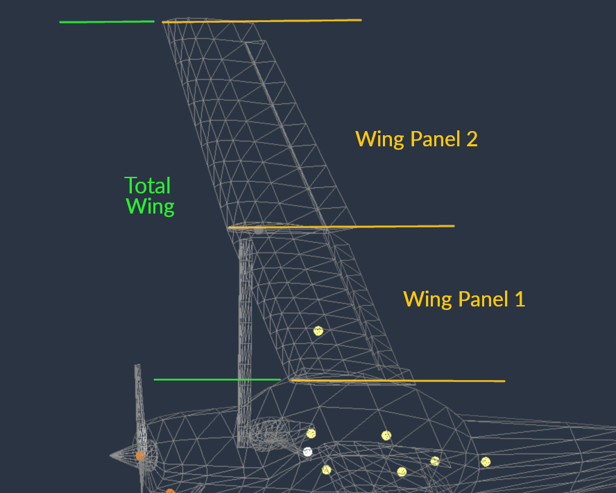
- A Wing Panel is a simple trapezoid. Each wing Tab: 1, 2, 3 and 4 configures a single wing panel. Stack multiple wing panels end to end to make a total wing for non-trapezoid wing planforms.
- A Total Wing is simply a generic term for an aircraft wing as a whole.
- Each wing Panel can have between 1 and 10 element strips.
- You can use up to 4 wing panels to make up a total wing.
- You can assign airfoils to wing sections(root & tip) in the EXPERT menu. We will not do that, but use default foils for this tutorial.
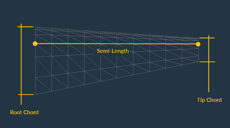
- Planform Shape Nomenclature (semi-length, root/tip chord): ->
- Wing Panel Planform Configuration Data Fields: ->
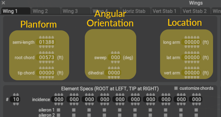
- Angular Orientation: (dihedral and sweep). Our project's wing have no dihedral or sweep. Experiment with these values to see their effect in the 3D view, but reset both to zero for the final configuration.
- Wing Location ->
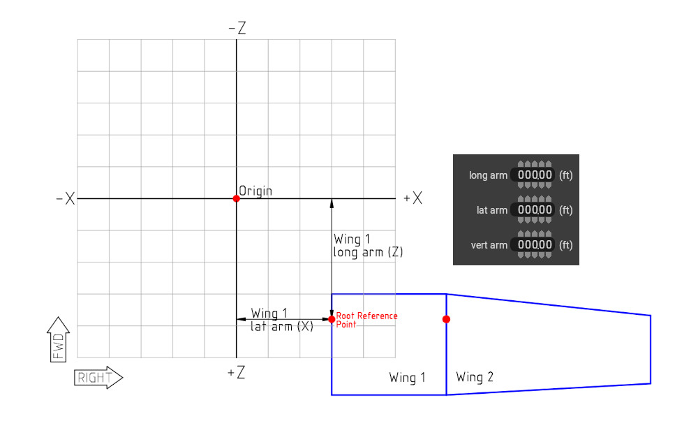 The location of the wing means the location of the quarter-chord reference point on the root chord. By quarter-chord, we mean the point is at a distance 25% of the root chord length, measured from the leading edge.
 - Wings 1-4 are symmetrical (Misc Wings are not)
Configure Wings & Stabilizers
Click to Enlarge
Use the above image to configure the Main Wing and Stabilizers. When complete, your aircraft will start to look like the X-1!
- Configure Main Wing
- Tip chord (you already configured root chord and semi-length.
- Wing Location (...that 25% point on the root chord!)
- Configure Horizontal Stabilizer
- Planform (root chord, tip chord, semi-length)
- Angular oriention (sweep)
- HorStab Location
- Configure Vertical Stabilizer
- Planform
- Angular Orientation (hint: 90º of dihedral = vertical wing)
- VertStab Location
Wing Flex
X-Plane simulates wing flex and the default settings are a bit too soft and the wings bend too much to be realistic for this aircraft. The X1 would fly fine with it, but it can look funny with a visible flight model. The real X1 have extremely short and stiff wings, so we are going to stiffen up the wings. Go to the following page and set the wing flex as shown in the icon image. Don't worry about understanding these settings, they are pretty intense. For now, just enter whats shown and we'll move on.
MENU PATH: Standard > Wings > Wing Flex Tab 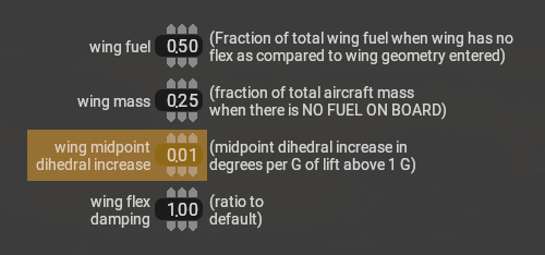
Step 7: Control Surfaces
In this step we are going to configure the control surfaces. There are two phases to this process, and each is done on differing PlaneMaker pages. The steps are:
- Assign Control Surface Types to Wing Elements
- Configure control surface sizes and deflection limits.
Assign Control Types to Wing Elements
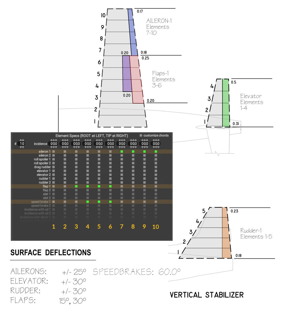
Control Element Assignment
Standard > Wings > Wing Tab 1 (and HorStab and VertStab Tabs after)
For this section, refer to the image at right. Every Wing / stabilizer Tab contains an Element Specs panel with a full listing of all available control surface types. In this panel you can configure how many element strips a Wing Panel has. There will be one column for each Element Strip present. Note that for the Horizontal Stabilizer, we have reduced the number of elements to 4, and for the Vert Stab: 5. Wing panels default to 10 element strips.
The checkboxes are used to specify the element strip you want a control to be on. If you study the image, you will see the correlation between the green checkboxes and the illustrated control locations. For example, the Flaps are on wing elements 3, 4, 5 and 6....so on the row labeled (flap 1), we highlight checkboxes 3, 4, 5 and 6. This says, 'we want flaps on these elements'. Remember, on this page we ONLY specify what TYPE of control, not their size. That comes in the section below.
You will note two sets of controls for each control type (1 and 2). This option is for more complex aircraft that use redundant systems for safety, i.e. Air Transport Category aircraft. For simple aircraft, we typically use the '1' set of controls only. Our X1 main wing have flaps, ailerons and speedbrakes. The horsstab only have an elevator, and the vert stab only a rudder.
Go through the main wing, horstab and vertstab tabs and configure the # of element strips and control types as shown in the image. Note that in that image, ONLY the main wing Element Specs panel and checkboxes are shown, not the stabilizer Tabs!!. You will have to examine the Stabilizer element drawings to infer their element strips and control type assignments! There will be no visible indication in the 3D view of these controls as they have no size yet. Next we will configure their size and movement.
Configure Control Surface Size and Deflection Limits
Before we configure the control surface sizes and movements, we first want to enable animation in the 3D view. If we do not do this, then the control surfaces can be difficult to see. We want and need the visual feedback of their movement to make sure we have configured them correctly. Enable animations via the menu: Special > Show with Still/Moving Controls. You can confirm this is enabled by observing the landing gear wheels rotating in the 3D view. Next up, the contol surface page.
MENU PATH: Standard > Control Geometry > Controls Tab
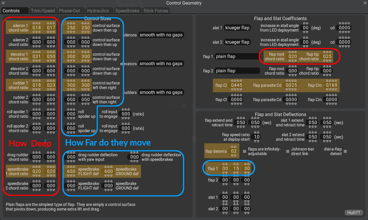
Controls Configuration CheatSheet
The image at right is a cheat sheet and have all the data field values you need to enter to configure the control surface geometry and movement. All of these values (except for the Flap Coefficients) were gleaned from the Control Element Assignement image above. There are generally four data values to enter per bi-directional (from a neutral point) control surfaces, i.e. ailerons, rudders and elevators.
- How deep (from the trailing edge) into the wing does the inboard side of the control go.
- How deep into the wing does the outboard side of the control go.
- How much does the control deflect (in degrees) UP
- How much does the control deflect DOWN
Flaps and speedbrakes are a bit different because they only deflect (from neutral) in one direction. For these control surfaces, you still have to configure the inboard and outboard chord ratios to size the control, but rather than configuring UP/DOWN deflection limits, you configure their target deflection angles at specific detents. Our project have 2 flap detent settings (UP / retracted) doesn't count as a detent, and our speedbrake one.
Regarding the Flap Cl, parasite Cd, and Cm coefficients, when flaps are deployed, they increase lift, drag and moment forces on the aircraft. These fields are used to specify how much coefficient to ADD to the nominal airfoil coefficients as the flaps are deployed. The values here were selected from an aerodynamics textbook for this particular flap configuration as a reasonable value for our flap configuration.
Use the cheatsheet above to enter the values highlighted in yellow, and cross reference these with the image above to understand why these values are set the way they are.
Step 8: Propulsion
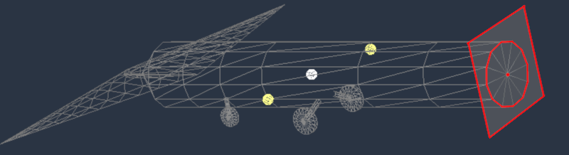
In this step we are going to specify the engine type, its power output and its location. In PlaneMaker, the location of the engine is the point where the propulsive force is applied to the aircraft frame. For our project it will be the tailpipe of the aircraft, but for a propeller configuration, it would be the center of the prop hub. lets head to the Engine Specs page.
MENU PATH: Standard > Engine Specs > Locations Tab
- Configure Engine Type, Thrust and Location:
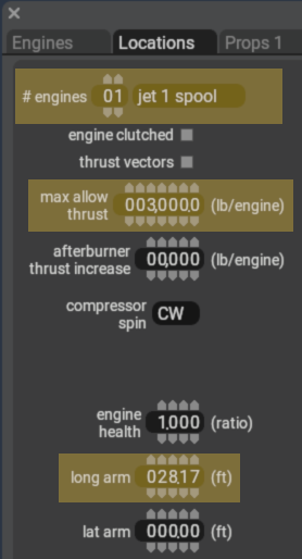
- A Jet 1 spool engine is a turbojet, and a Jet 2 spool type is a TurboFan
- 3000lbs of thrust and its located at the very back of the aircraft tailpipe!
MENU PATH: Standard > Engine Specs > Jets 3 Tab
- Configure Compressor Area:
Jets 3 Tab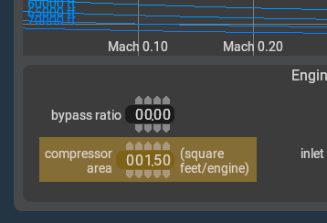
- Compressor Area is required for computing jet thrust. If you forget to enter this and try to save the aircraft, PlaneMaker will let you know its not happy.
Now save your aircraft, you've reached a milestone!
File > Save
Congratulations! Your plane is now Flyable in X-Plane
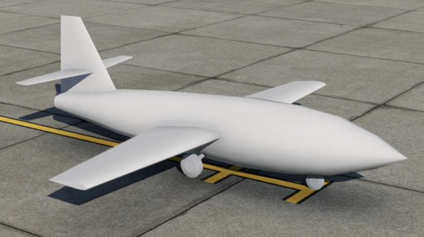
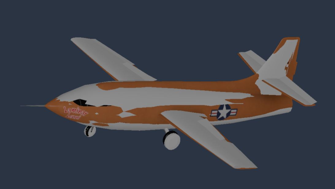
Click to Enlarge
If you open your aircraft in X-Plane now (or reload it from the Developer Menu), it should look as shown at right. If you want to fly it in X-Plane now to get a quick fix, you'll need to start with engines running. Note that X-Plane will add a prefs file to your faircraft older if you open/close it in X-Plane. You can ignore this file, its for X-Plane's use.
What you are seeing is referred to in a few differing ways: Flight Model Geometry, or PlaneMaker Geometry, or Physics Model. This distinguishes it from the Eye Candy 3D Geometry we'll add next. Your aircraft now have enough flight model elements to operate on the ground and in the air with stability:
- Wings to lift it off the ground.
- Control Surfaces to maneuver it in the air.
- Longitudinal Stability to make it controllable.
- Fuel to feed the propulsion unit.
- Propulsion to push it though the air.
- Landing Gear, for efficient ground / air transition.
This is a phase where aircraft authors can begin to do flight testing to tweak design elements; however, it is still clearly missing some things. We have:
- No Instruments!
- No Visually Accurate Model.
Let's add those elements!
Step 9: Add Visual Models
In this step we are going to add some eye candy 3D Objects and attach them to the aircraft. In addition, we will hide the PlaneMaker Physics Model so it will not render in X-Plane. Afterwards, our aircraft will look like we expect an X1 aircraft to look.
First, double check your aircraft folder and ensure that your objects folder contain 3 files in it as described in Step 1: Project Structure. These 3D objects were created in advance for you using the Blender® 3D application, and their creation is beyond the scope of this tutorial. Suffice to say Blender is the official tool we use at Laminar to build visual 3D models, configure them to work with X-Plane and export them out to X-Plane's OBJ format.
Attach OBJs
MENU PATH: Standard > Objects
- Hit the
ADDbutton twice. This creates TWO slots to attach our two OBJ files. - Attach Each OBJ file to the aircraft
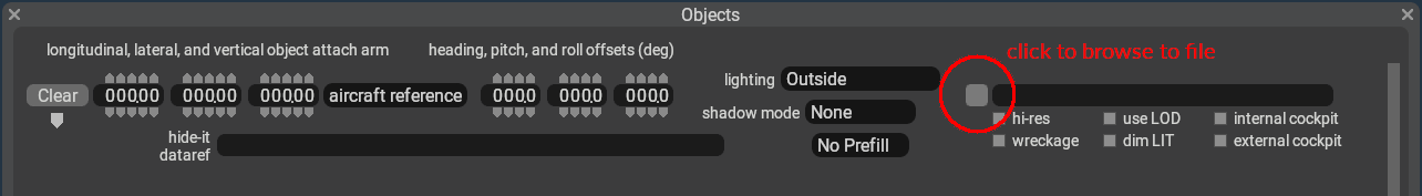 . The order you select them does not matter here. For certain complex situations, order can matter, but most of the time it does not.
 - After import, set both Objects' Shadow Mode pulldown to All Views. This tells X-Plane to render these OBJ shadows onto the ground from inside cockpit views and external camera views. If you have a 3D OBJ of something like rudder pedals, then that would be an example of something you would NOT want to render shadows for, i.e. shadows = none.
Click to Enlarge
Note that after you import the 3D Objects, they align with the flight model geometry. This is because the origin of the visual 3D models (in Blender) is the same as the origin of the PlaneMaker aircraft model. This does not have to be the case. In each OBJ parameter settings, you can move them around and even rotate them with their translational and rotational parameters. Alternatively, you can attach an OBJ to other entities via a pull down, in which case the global origin of the visual 3D OBJ model will align with the local origin of the PlaneMaker entity (wing, gear, etc). This could be used with 3D OBJs representing wing tanks or wheel pants, etc. Lets hide the physics geometry next.
Hide Physics Geometry
MENU PATH: Expert > Invisible Parts 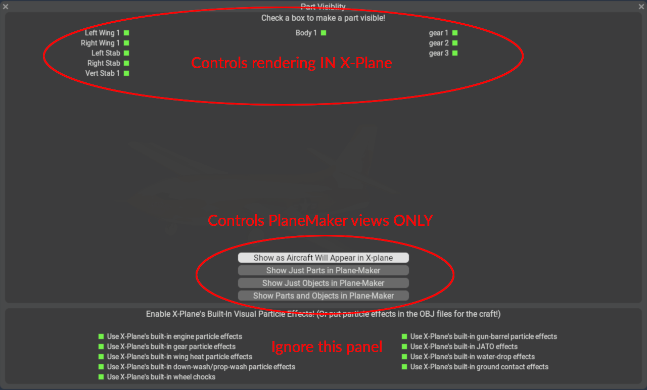
The top of part of the visibility panel shows all the PlaneMaker Parts you have configured for your aircraft and the checkboxes that are green tell X-Plane to render that PlaneMaker geometry. We want to uncheck all of these, so X-Plane will not render them, and only render our visual OBJ models.
NOTE that there is a PlaneMaker quirk here. For symmetrical entities like Primary wing panels and horizontal stabilizer, you cannot hide one side and leave the other visible. If you click a checkbox for something like the Left Wing 1 and nothing happens, then simply click the Right Wing 1 and both will be disabled. Basically, click all boxes until none are green/checked.
The bottom part of the visibility panel have four buttons that allow you to control the visibilities of the Physics and visual models in PlaneMaker. These have NO effect on what renders in X-Plane, only the checkboxes above do. In general, these allow you to see your physics model in PlaneMaker after you configured them to be hidden. If you now click the Show Just Parts in PlaneMaker button, you will see your visual model disappear and only display your physics model. Set these however you need to work in PlaneMaker.
NOTE
Be aware that as you utilize the four visibility buttons, you may see some green checkboxes you disabled previously re-appear. This is simply PlaneMaker doing what it needs to in order change the visibilities in the editing window. Ultimately use the Show as Aircraft Will Appear in X-Plane button to see what your final visibilities configuration will be in X-Plane.
Lets move on to the final Step, adding some 2D panel instruments!
Step 10: 2D Panel Instruments
Nowadays few people use 2D instruments, as we are so used to 3D; however, they are very effective during the early prototyping phase of aircraft design when one is calibrating the aircraft performance and tweaking the flight model. We are going to demonstrate two methods of adding 2D Instruments.
- Importing instruments exported from another aircraft.
- Adding instruments from PlaneMaker's 2D instrument library
Head over to PlaneMaker's 2D Panel editor.
MENU PATH: Standard > Panel: 2-D
The first thing to notice is the background panel image is that of a typical light GA. This background image is selected based on the 2D Cockpit pulldown type set at Standard > Viewpoint > General Tab1 > Cockpit Panel. If you go change that pulldown to something like Glider or Airliner, then the background image will change. Go change it to Fighter and then come back to the 2D Panel editing page.
Click to Enlarge
Next we are going to import some instruments we prepared previously for this project. This is a PlaneMaker feature whereby you can create a 2D panel layout in one aircraft, then export out that layout and replicate it in another aircraft. The exported file in this scenario is a *.panl file type and this file specifies which instruments to place on the panel, where to place them and how they are configured.
- Download *.panl file and save it to your Aircraft Folder.
- Import the PANL file into PlaneMaker
After import, your panel should look as shown at right. We have included:
- Altimeter
- Brake annunciator
- Engine N1 indicator
- Throttle lever
- Flap position indicator
- Speedbrake lever
- Fuel Gauge
- EGT Gauge
...and so that you can start the engine from a cold and dark state, we also included the following controls. Without these you could only fly your aircraft if you started the flight with engines running:
- Battery switch, to power the electric starter (default starter type)
- Igniter switch to light the jet engine.
- Fuel switch to enable fuel to the engine
- Starter Button
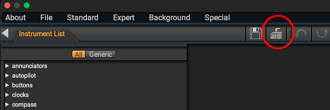
Click to Enlarge
Next we will add the following instruments from PlaneMakers instrument list, which is a hierarchical directory. Browse the Instrument List and find the instruments below and drag them out onto the panel. You can drag either the preview image OR the text listing of the instrument, both will work. The instrument path to these instruments are:
- standard six > artificial horizons > all_attitude.png
- standard six > airspeed > ASI_preset_HM.png
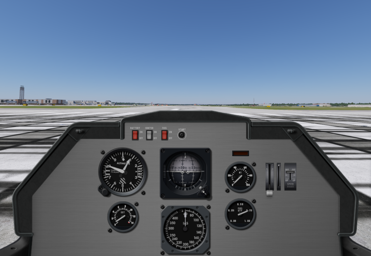
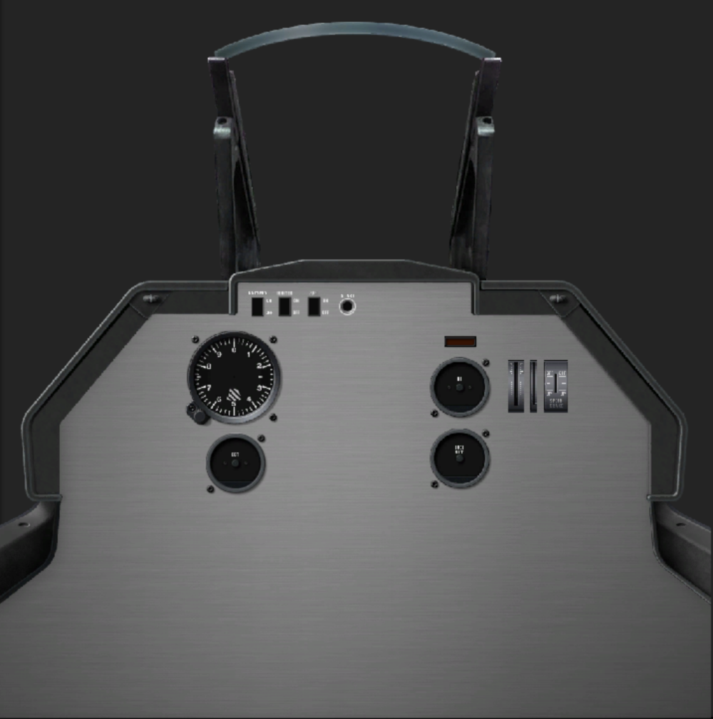
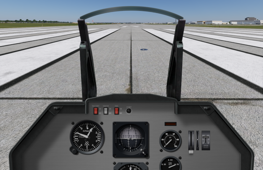
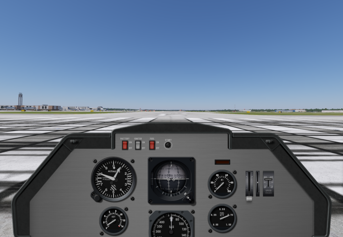
Save the aircraft and reload it in X-Plane. With all the instruments in place, your aircraft panel view should look pretty close to whats shown at right, depending of course where you put the last two instruments above.
This looks pretty good, except that we appear to be staring at the ground. What we need is for the horizon line to be a bit lower, it is way too close to the top of the screen. If we lower it in the screen, it will make the view look more normal. We can adjust that horizon line location via the following location in PlaneMaker. Change the value to that shown in the pop-up and reload the aircraft:
Standard > Viewpoint > Cockpit Tab > Screen Centers Panel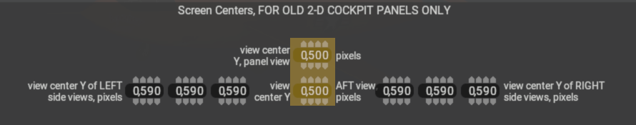
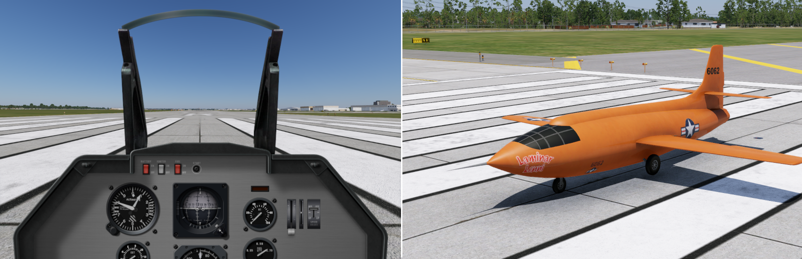
If everything has gone according to plan, you should have a well flying X1 that looks as shown lower right, with a panel as shown lower left. You should be able to operate the aircraft whether starting cold and dark, or with engines running. As you fly it in X-Plane, remember that this is a relatively HOT design. It has a short wingspan and it stalls around 110 knots and though it has speed brakes, it does not slow down easily. It has stubby gear so do not rotate it to aggressively on takeoff. You will need to build up a fair amount of speed and let it get off the runway a bit before you start playing fighter pilot!
We hope you learned something through this processes and we have a little extra step below if you care to learn a little bit more about customization and remove the HUD frame. If you don't want to remove the HUD, then feel free to go into the 2D Panel editor and add HUD elements to the HUD.
All Done! ....almost
To really complete your aircraft pacakge, open X-Plane's Aircraft selection window and select your aircraft. Then click on the Customize button, and in the upper right hand corner of the preview screen, you'll see a button labeled Generate Icon. Hit that and X-Plane will take a few seconds to build you a preview icon and add it to your aircraft folder. NOW you can share your aircraft folder with others and they can browse and load it in X-Plane too!
Step 11: Extra - Remove HUD Frame
Click to Enlarge
In this optional step, we are going to dive a bit deeper into customization. We're going to modify that background image and erase the HUD and lower the horizon a tiny bit more to compensate. You'll need an image editor to edit the background image and erase some pixels.
So the way customization works for 2D panels, is that X-Plane looks in your aircraft folder for very specific folders and file names, and if it finds them, it loads YOUR files instead of the default files. So what we do then is create the necessary folders and files in your aircraft folder and name them what X-Plane expects them to be.
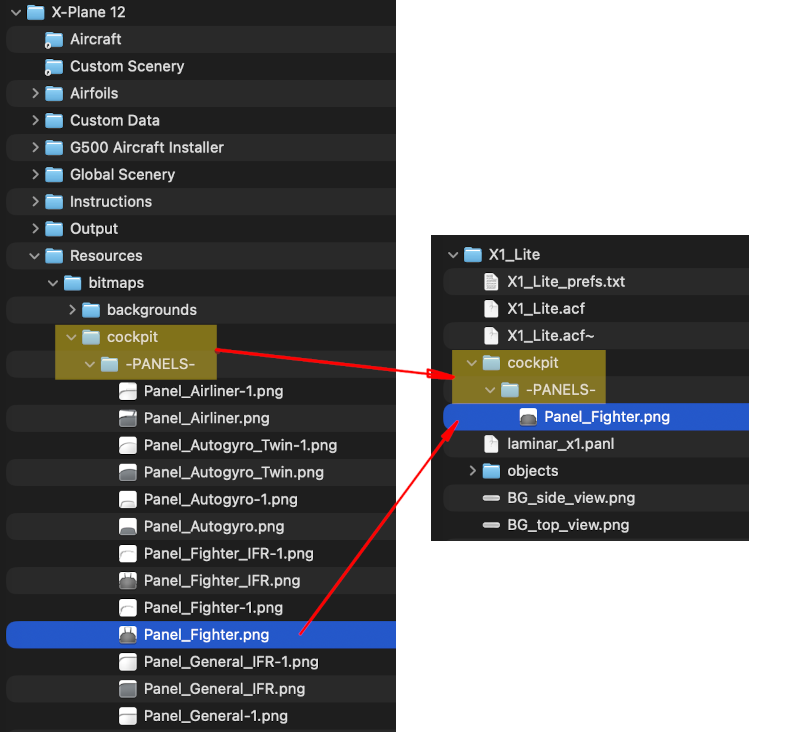
In the image at right, the left side is the default path X-Plane uses to load the Fighter panel background. On the right side is our aircraft project, but with some added folders and files. Note how our directory names match the default one?
This panel customization paradigm was established well over 20 years ago to customize 2D panels. As aircraft authors, we just memorize how we were told to do it. We create a cockpit folder in our aircraft folder, we then put a -PANELS- folder inside of that, and finally, we put our custom panel image in there, and we name that image specifically to match the standard file names X-Plane uses for its 2D panel backgrounds. Again, the background image selected depends on what type of aircraft you select in PlaneMaker, as we did in Step 10 when we set it to Fighter.
Click to Enlarge
So create those two folders, and copy over the Panel_Fighter.png texture from X-Plane's Resources directory and after you do that, PlaneMaker and X-Plane will use the texture in your aircraft folder. FYI, there is a Refresh Textures button in PlaneMaker on the 2D Panel Editor window. You can hit this button to see any changes you make to the texture (assuming you remember to save it) without relaunching PlaneMaker.
You can now erase out the HUD and alter the view center down to about 450px to shift the horizon down a bit further. The image at left shows how ours looks these modifications:
Next we notice that some of the instruments are a bit cut-off below the bottom of the window. Ideally we'd like to shift the whole panel up just a bit so we can see the airspeed indicator fully. We make this adjustment at:
Standard > Viewpoint > Cockpit Tab > Aircraft and Panel Visibility Panel.
Configure the values highlighted as shown: 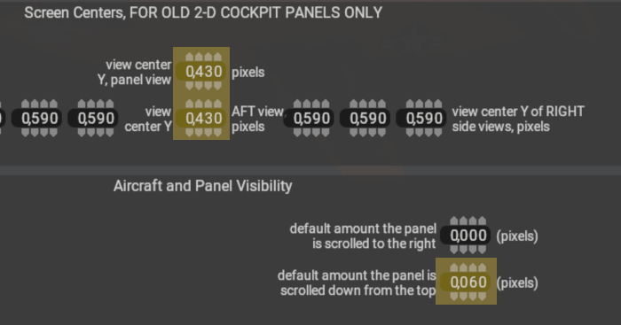 . The change in the lower right value shifts the panel up, and the two view center values shift the horizon line back down a bit. From here, you can play with these values, and indeed move instruments around in the panel editor if you want to tighten everthing up. Below is our final configuration after adjusting the panel and horizon line heights. It has a pretty good feel! Thank you for participating in this tutorial, we hope you had success and learned some fundamentals about building aircraft in PlaneMaker!